
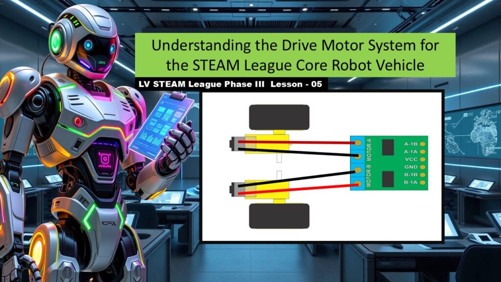
In this lesson, students finally learn how their robot moves. They explore how the H-bridge sends signals to each motor, how transistors act like tiny valves that control power, and how the robot’s left and right wheels receive independent commands. Students also learn how torque, speed, and direction come from simple electrical choices. This lesson bridges the gap between wiring and true motion, helping students feel confident as they bring their Auto-Bot to life.
Student Learning Goals
By the end of this lesson students will be able to
• Identify the robot’s right and left sides using consistent orientation
• Explain how the H-bridge and its transistors control each motor
• Understand how direction is determined using A1, A2, B1, and B2
• Describe how torque and speed change with different power levels
• Use simple steps to test and verify proper wheel movement
Materials Needed
Partially assembled Auto-Bot chassis (from Lesson 03)
H-bridge attached to the robot
Motors and wheels installed
Battery pack
Arduino and USB cable
Projector or printouts of slides
Teacher Preparation Notes
This lesson builds on what students learned in Lesson 04, but you don’t need to reteach the technology. Today is about connecting knowledge to movement. Be patient. Students often get confused about “left” and “right” when working upside down or sideways. Always orient the robot so the students are looking from the back toward the front.
Plan to demonstrate motor testing slowly. Students may need to try several times before their wheels move in the correct direction. Remind them that frustration is normal and part of the engineering process.
Safety Notes
Keep fingers clear of spinning wheels
Make sure loose wires are tucked away before powering the motors
Never power motors from the Arduino directly
Move slowly when testing to avoid sudden jumps
Warm Up Activity
Ask students
If the robot wants to turn left, what should the wheels do
Let them reason it out. This warms up their thinking and prepares them for deeper understanding about wheel control.
Lesson Flow
Step One – Understanding Robot Orientation
Show students how to describe the robot just like a person
When you look from the back toward the front
The robot’s right side is on your right
The right drive wheel matches your right arm
This step prevents confusion later when wiring and code refer to “right motor” and “left motor.”
Step Two – What Is Inside the H-Bridge
Explain that the H-bridge uses transistors
Transistors work like valves in a water line
A small signal lets a little electricity through
A stronger signal lets much more through
This is the foundation for speed and direction control.
Step Three – Motor Control Lines
Introduce the four control lines
A1 and A2 control the right motor
B1 and B2 control the left motor
A tiny signal on A1 creates movement on the right wheel
Teacher note
Students do not need to memorize everything now. Repetition in coding lessons will lock this in.
Step Four – Motors and Gears
Show the motor and explain its purpose
The 125 RPM motor provides smooth, strong movement
It uses a gear reduction so the robot has enough torque to push itself across the floor
Let students feel how the motor turns by hand. This makes the gear reduction real.
Step Five – Setting Direction
Explain how direction is chosen
Full power on A1 and zero on A2 makes the right motor turn one way
Full power on A2 and zero on A1 reverses it
The same is true for B1/B2 on the left wheel
This shows students the simplest relationship between electricity and movement.
Step Six – Understanding Torque and Speed
Show how changing the strength of the signal changes the motor’s behavior
Lower power = gentle, slower turning
Higher power = faster, stronger motion
Explain that the robot will later use low power for careful steering and higher power for straightaways.
Step Seven – H-Bridge Motor Connections
Review the wiring pattern
Right motor red wire → A1
Right motor black wire → A2
Left motor red wire → B2
Left motor black wire → B1
Teacher note
This is also where students discover if any wires need flipping.
Step Eight – Why PWM Matters
Explain that PWM (Pulse Width Modulation) lets the Arduino send fast pulses of power
Short pulses = low speed
Long pulses = high speed
This connects back to earlier lessons where they saw PWM in code.
Step Nine – Testing One Wheel at a Time
Walk students through the recommended process
Make one wheel turn
Make sure it turns the correct direction
Make two wheels turn
Make sure both turn the correct direction
Teacher note
Students often feel overwhelmed trying to test everything at once. Remind them that engineering always starts small and builds upward.
Teacher Notes for Slides
Orientation slides
Use physical demonstrations. Students understand much faster when they see it.
Transistor slides
Explain that students don’t need formal electronics knowledge. The analogy is enough.
Torque and direction slides
Encourage students to visualize steering like a shopping cart or wheelchair.
Connection pattern slides
Reassure students that wrong direction isn’t a failure. It’s a sign to swap wires.
Testing slides
Celebrate every small success. Even getting one wheel turning correctly is a win.
Independent or Group Activity
Students test their robot’s wheels using simple directional commands from the Arduino.
They answer
Did the right wheel move the correct way
Did the left
If not, what should we swap or adjust
This builds understanding through authentic experimentation.
Vocabulary and Concepts
Torque
The twisting force that helps the robot move.
Direction Control
Choosing which way a wheel spins.
PWM
Tiny bursts of electricity that change speed.
Control Lines
Electrical signals that tell the motors what to do.
Wrap Up
Ask students
What did you notice when the motors changed speed
How did it feel seeing your robot move for the first time
Celebrate this moment. It is one of the most exciting parts of Phase III.
Exit Ticket
Write one new thing you learned about how the robot moves
Write one thing you want to understand better
Quiz
- Which side is the robot’s right side
- What do A1 and A2 control
- What does increasing power do to the motor
- What does PWM help the robot do
- Why do we test one wheel at a time
Teacher Reflection
Did students grasp the idea of direction control
Were any students confused by left and right orientation
Did motor testing bring excitement or frustration
Make notes for wiring day so you can support them where needed.