
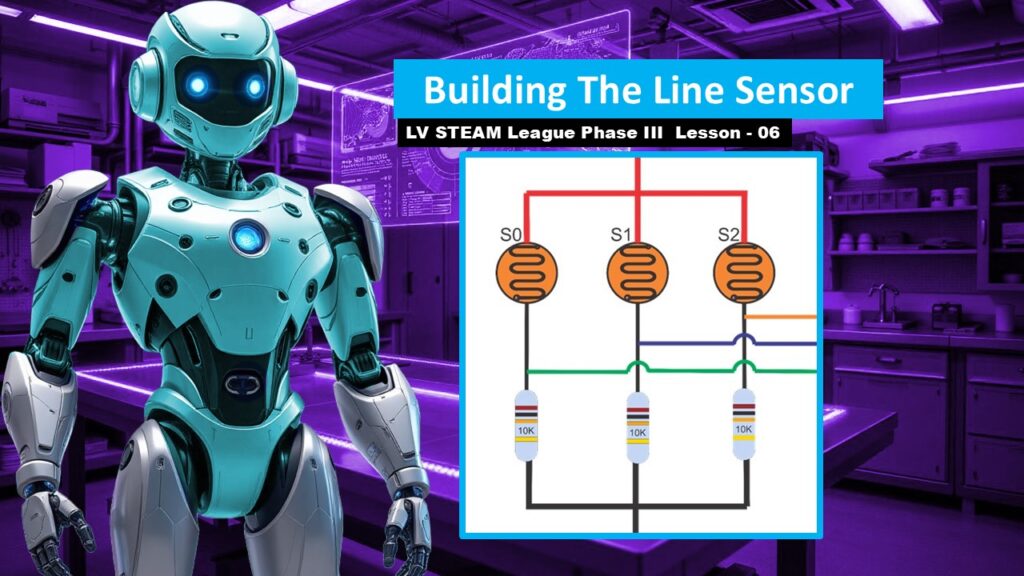
In this lesson, students build the “eyes” of the Auto-Bot. They create a three-sensor light array that helps the robot detect the dark line on the track. This is a hands-on electronics activity where students twist, connect, solder, and heat-shrink simple components into a working harness. The goal today isn’t coding or testing. It’s helping students feel confident building a small circuit with their hands and understanding how these tiny parts will later guide their robot.
Student Learning Goals
By the end of this lesson students will be able to
• Identify the parts used to create a line-follower sensor
• Explain how photoresistors react to light and dark surfaces
• Assemble a three-sensor harness using resistors, wires, and heat-shrink
• Understand why secure connections matter for consistent readings
• Prepare the finished sensor for installation in a later lesson
Materials Needed
3 photoresistors
3 ten-k resistors
Five short wires (various colors)
Five pieces of heat-shrink tubing
Soldering iron and solder
Wire cutters/strippers
Heat source for heat-shrink (heat gun or lighter)
Optional: helping hands clamp for holding parts
Teacher Preparation Notes
Lay out all parts before students arrive. The small size of components can feel intimidating for beginners, so neatly arranged materials help calm nerves.
You may choose to demonstrate the soldering yourself. Students can twist wires if needed, but the slides note that soldering creates a stronger, longer-lasting connection for repeated track use.
Move slowly, and remind students that this lesson is not about perfection. It’s about building something delicate and useful with patience and teamwork.
Safety Notes
Keep soldering equipment in a designated, supervised area
Hot tools stay on heat-safe pads only
Students should hold wires with pliers, not fingers, while soldering
Heat-shrink should be warmed gently and away from skin
Everyone wears eye protection
Warm Up Activity
Show a single photoresistor and ask
What do you think this tiny part can sense
Let students guess things like light, color, or brightness.
This builds curiosity before the hands-on activity.
Lesson Flow
Step One – Understanding the Sensor Build
Explain that the robot’s ability to follow a line begins with three tiny sensors
Left
Center
Right
Students will build a harness that ties them together so the Arduino can read their values.
Teacher note
Remind students that this small circuit will become incredibly useful later when they start coding.
Step Two – Creating the Resistor/Sensor Pairs
Students begin by twisting one leg of a 10k resistor and one leg of a photoresistor together.
Repeat for all three sets.
Teacher tip
Make sure the heat-shrink tubing is already on the wires before twisting. Students always forget this step.
Step Three – Adding the Signal Wires
Each twisted pair gets a colored wire.
Students twist the wire in, then solder and heat-shrink the connection.
Explain that each of these colored wires will later plug into A0, A1, and A2 on the Arduino.
Step Four – Creating the Shared Positive Line
Students twist all three open legs from the photoresistors together.
Then they solder the red wire to that connection.
This creates the 5-volt line that powers all three sensors.
Step Five – Creating the Shared Ground Line
Students twist all the remaining legs from the 10k resistors together.
Then they solder and heat-shrink the black wire to create the ground line.
Teacher note
Explain that every circuit needs a positive and a ground. This is the simplest version of that concept.
Step Six – Reviewing the Completed Harness
Hold up a finished sensor harness
Three signal wires (one per sensor)
One shared red wire (power)
One shared black wire (ground)
Tell students
This tiny bundle will give your robot the ability to see the world beneath it.
Step Seven – Previewing Installation
Explain that installation happens during Lesson 07 when the robot is fully wired.
Today is only assembly.
Teacher note
Knowing installation comes later helps students stay present and not feel overwhelmed.
Teacher Notes for Slides
Educator Information
Remind teachers that soldering is preferred but optional. Show both methods if needed.
Twisting and soldering steps
Move slowly. Students may need to see each twist twice.
Shared wire connections
This is the most confusing part. Use a visual demonstration and repeat the purpose of each connection.
Harness complete slide
Pause here. It’s a moment of pride. Students built a real sensor system.
Independent or Group Activity
Have students label each of their three signal wires
Left
Center
Right
This helps prevent confusion in the wiring lesson and helps students feel organized and confident.
Vocabulary and Concepts
Photoresistor
A sensor that changes resistance based on light.
Resistor
A small part that helps manage the flow of electricity.
Heat-shrink
Tubing that seals and strengthens wire connections when heated.
Sensor Array
A group of sensors that work together to read the world.
Wrap Up
Ask students
What was the trickiest part of building your sensor
What surprised you about how small these parts are
Celebrate their effort. This is delicate work, and completing it is a big accomplishment.
Exit Ticket
Write one thing your line sensor will help the robot do
Write one question you have about how the robot will use this information
Quiz
- What does a photoresistor detect
- Why do we use 10k resistors in this circuit
- What color wire carries power in the sensor harness
- What color wire carries ground
- How many sensors are in the array
Teacher Reflection
Did students seem comfortable with small components
Did anyone struggle with the twisting or soldering steps
Would a future class benefit from more demonstration time
Use this reflection to support students during wiring in Lesson 07.