
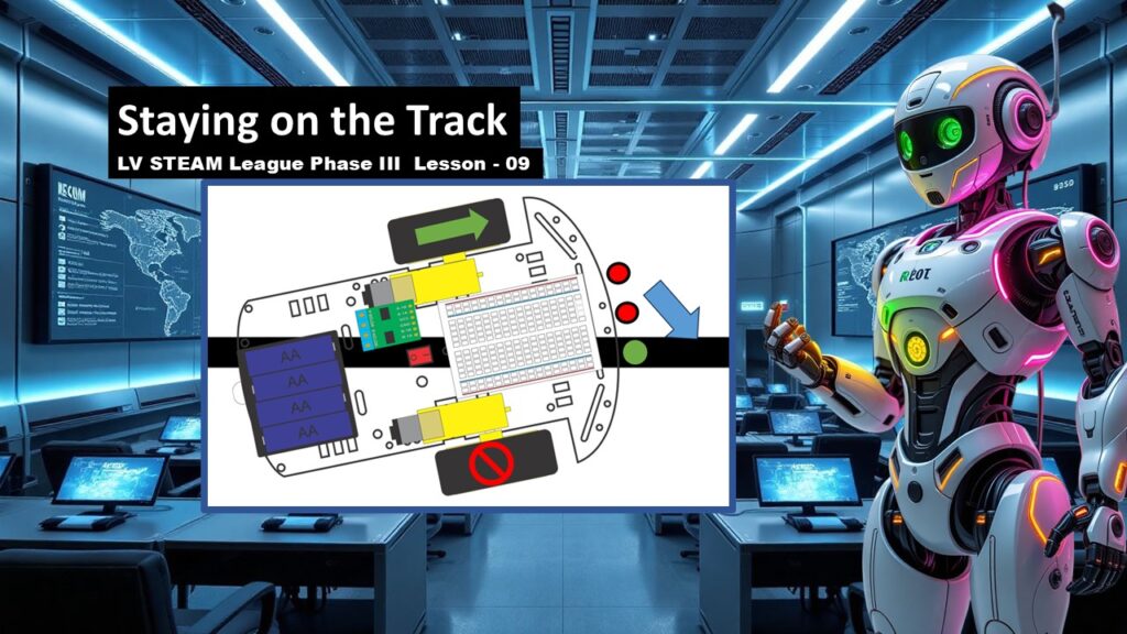
This is the moment students have been working toward since Phase I. In this lesson, their Auto-Bot becomes an autonomous robot that can sense the world and respond to it. Students learn how the three light sensors detect the line, how the Arduino reads these values, and how simple if/else logic tells the robot when to go straight, turn left, turn right, or stop. Everything they have learned — wiring, sensors, motors, logic, and code — comes together here. Today is a day of excitement, discovery, and celebration.
Student Learning Goals
By the end of this lesson students will be able to
• Explain how a photoresistor works and why robots use them
• Use analogRead to measure sensor values from A0, A1, and A2
• Understand how the Arduino turns sensor readings into decisions
• Write simple if/else code to guide the robot along the track
• Test, adjust, and refine their robot’s line-following behavior
Materials Needed
Fully wired Auto-Bot (from Lesson 07)
Arduino Micro with USB cable
Laptop with Arduino IDE
Printed track or sample dark line
Sensor array installed on the front of the robot
Battery pack
Optional: tape markers for testing areas
Teacher Preparation Notes
Students will experience both excitement and frustration today. This is normal. Encourage them to test often and make small adjustments. The goal is not perfection — it is learning how to read sensor values and respond with clear, simple logic.
Have students start by reading sensor values before attaching wheels to the ground. This prevents runaway robots and helps them understand the data calmly before applying movement.
Make sure the room has a well-lit, consistent testing area. Light levels affect sensor values.
Safety Notes
Keep the robot lifted off the table during initial motor tests
Make sure loose hair, sleeves, and fingers stay clear of wheels
Do not touch exposed wires while the robot is powered
Move slowly and power off between adjustments
Warm Up Activity
Hold the robot above the track and ask
What do you think the robot sees when it is over the dark line
Let students guess before revealing how the sensors read light and dark.
Lesson Flow
Step One – Understanding Photoresistors
Explain the key idea in simple language
A photoresistor changes its resistance when light hits it
More light = lower resistance
Less light (over the dark line) = higher resistance
Help students see that their robot is not “seeing” color — it is sensing brightness.
Step Two – Reading Sensor Values with analogRead()
Demonstrate how analogRead converts voltage into numbers between 0 and 1023
Explain that this lets the robot measure how bright or dark a surface is
Show the starter code
void setup() {
  Serial.begin(9600);
}

void loop() {
  Serial.println( analogRead(A0) );
}
Teacher note
This is the moment students begin to see the connection between electronics and programming.
Step Three – Testing the Sensor Values
Have students move the robot gently over the line
Watch how the readings change
Light area = low number
Dark line = high number
This builds intuition they need for the if/else logic.
Step Four – Applying If/Else Logic
Introduce how the robot makes decisions
if (value < 500) {
  // action A
} else {
  // action B
}
Explain gently that the robot will compare sensor values and “choose” an action.
Teacher note
Keep this simple. They don’t need complex branching yet.
Step Five – Mounting the Sensor Array
Show how the three sensors sit in front of the robot
Left
Center
Right
Explain that together, they tell the robot whether the line is under the left, center, or right side.
Step Six – Understanding Robot Behavior
Walk through each scenario with the class
1. Center sensor sees the line
Both wheels forward → robot goes straight
2. Right sensor sees the line
Stop right wheel, drive left wheel → robot turns right
3. Left sensor sees the line
Stop left wheel, drive right wheel → robot turns left
4. None of the sensors see the line
Stop both wheels → robot is lost
Teacher note
Celebrate that these four rules create a fully autonomous robot.
Step Seven – Bringing Everything Together
Explain their achievement
You already know
• how to read sensors
• how to use an H-bridge
• how to drive motors
• how to use if/else
Now we combine them to follow the track.
Let students begin writing their first full line-following program.
Teacher Notes for Slides
Photoresistor slide
Explain slowly. This is the foundation of the entire challenge.
analogRead slides
Use humor if needed. These numbers are strange at first but quickly become familiar.
Logic slides
Encourage students to think about the robot like a little decision-maker.
Behavior diagrams
Students love these moments. Every diagram feels like unlocking a secret of robotics.
Final encouragement slide
Students feel excited but nervous. Reassure them that they already know the core pieces.
Independent or Group Activity
Have students write a simple decision tree on paper
If center sees line → go straight
If right sees line → turn right
If left sees line → turn left
If none see line → stop
This helps them organize thoughts before coding.
Vocabulary and Concepts
Photoresistor / LDR
A sensor that responds to light.
analogRead()
Reads voltage and turns it into a number.
If/Else logic
Code that chooses between actions.
Autonomous behavior
The robot acting without human control.
Wrap Up
Ask students
What was the most exciting part of seeing your robot respond to the line
Let them share, celebrate, and feel proud.
They are not just building a robot — they are building confidence.
Exit Ticket
Write one thing your robot understood today
Write one thing you want to improve in your code next time
Quiz
- What does a photoresistor detect
- What number range does analogRead() return
- What does the robot do when the center sensor sees the line
- What does the robot do when none of the sensors see the line
- Why do we use if/else statements
Teacher Reflection
Did students understand the sensor readings
Were they able to translate logic into code
Did robots respond in expected ways or need adjustments
Use these notes for tuning future support.