
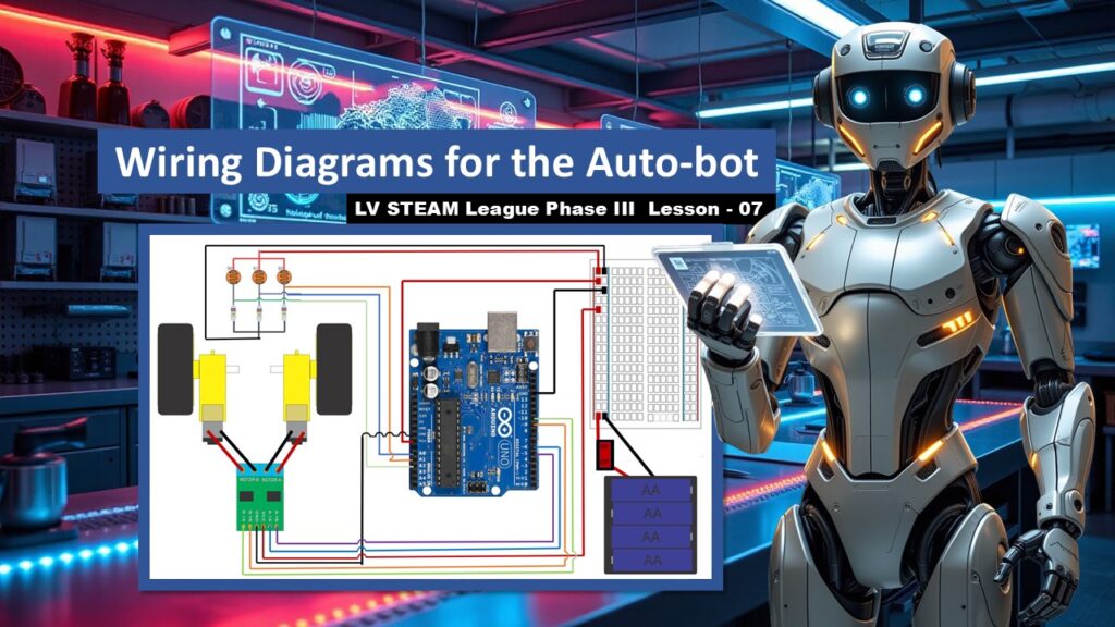
In this lesson students bring their robot to life by connecting every electrical part into a complete working system. Today is not about coding or movement. It is about taking the time to make thoughtful, careful connections so the Auto-Bot has clean power, working motors, and readable sensors. By the end of class, the robot will be fully wired and ready for programming in the upcoming lessons. This is an exciting milestone, and students often feel proud seeing their robot “become real” for the first time.
Student Learning Goals
By the end of this lesson students will be able to
• Identify where each major component connects on the robot
• Safely wire the power switch, battery pack, Arduino, and H-bridge
• Connect each motor to the correct control pins
• Attach the sensor array and understand which wires go to A0, A1, and A2
• Build confidence reading wiring diagrams and assembling circuits step by step
Materials Needed
Assembled Auto-Bot chassis
Battery box
Breadboard
Arduino
H-bridge
Both drive motors
Sensor array harness (from Lesson 06)
Jumpers and connecting wires
Small screwdriver
Teacher Preparation Notes
Wiring days can feel overwhelming to students, especially those who fear “breaking something.” Move slowly and reassure them that mistakes are normal and fixable. It helps to model the wiring on a projector or document camera, showing one connection at a time.
Encourage students to gently tug each wire after placing it. A loose wire is the number one cause of robot problems. Keep the atmosphere calm and patient.
Safety Notes
Power OFF during all connections
Do not touch bare wires together once power is connected
Keep the battery pack unplugged until the very end
Move carefully around spinning wheels during testing in future lessons
Warm Up Activity
Ask students
Why do you think wiring matters so much for a robot
Let them share ideas about power, signals, and communication between parts.
This helps them enter the lesson with a sense of purpose.
Lesson Flow
Step One – Understanding the System
Show the diagram of all the robot parts that must be connected
Battery box
Breadboard
Arduino
H-bridge
Gear motors
Sensor array
On/off switch
Explain that today they will link these parts the same way a nervous system links organs in a body.
Step Two – Wiring the Power Switch and Ground
Students connect
Red battery wire → first post on the switch
Second switch post → positive rail on the breadboard
Black ground wire → ground rail on the breadboard
Teacher note
Tell students they are building the robot’s heartbeat. Power begins right here.
Step Three – Supplying Power to the Arduino
Students connect
Arduino VIN → positive breadboard rail
Arduino GND → ground breadboard rail
Reassure students that the Arduino has simple needs: one wire for power, one for ground.
Step Four – Connecting the Motors to the H-Bridge
Students attach both motors to the H-bridge
Motor wires must go to either the A side or the B side
Consistency matters, not direction yet
Teacher tip
If a wheel spins backward later, we just swap wires. No stress.
Step Five – Powering the H-Bridge
Explain the two wiring options
Option 1
H-bridge VIN → positive rail
H-bridge GND → Arduino GND
Option 2
H-bridge VIN → positive rail
H-bridge GND → ground rail on the breadboard
Either option is correct. Choose whichever matches your classroom build.
Step Six – Connecting the Motors to Arduino Pins
Right motor
Pin ~5 → Motor A1
Pin ~6 → Motor A2
Left motor
Pin ~9 → Motor B1
Pin ~10 → Motor B2
Explain that these pins allow the Arduino to send speed and direction commands to each wheel.
Step Seven – Adding the Sensor Array Power
Students connect
Sensor red wire → Arduino 5V
Sensor black wire → Arduino GND
Teacher note
The sensor array needs clean power so it can “see” light and dark clearly.
Step Eight – Connecting the Sensor Array Signals
Signal wires connect to the analog pins
Center sensor → A0
Right sensor → A1
Left sensor → A2
Highlight that these sensors tell the robot where the line is on the track.
Step Nine – Reviewing the Completed Wiring
Show the final slides
Wiring now includes
Power
Motors
Control lines
Sensors
All grounded correctly
Tell students
Your robot is fully wired. The next lessons teach it how to think.
Teacher Notes for Slides
Slides that show the full system
Pause and explain each part. Students need the big picture.
Slides showing the power switch
Reassure them: getting this right prevents 90 percent of future issues.
Slides showing motor connections
Encourage students not to worry about direction yet.
Slides showing sensor connections
Help them label their signal wires to avoid confusion.
Slides marking “Completed”
Let students feel proud. This is a major milestone.
Independent or Group Activity
Have students check each other’s wiring using a simple checklist
Is the switch connected correctly
Is VIN connected to positive
Are motors in the correct A/B sides
Are sensors plugged into A0, A1, A2
Peer review builds confidence and reduces errors.
Vocabulary and Concepts
VIN
The voltage-in pin that provides power to the Arduino.
Breadboard
A board that lets us make temporary electrical connections.
Ground (GND)
The return path for electricity. Every circuit needs it.
Control pins
Signals from the Arduino that tell the robot how to move.
Sensor array
The robot’s three “eyes” for following the track.
Wrap Up
Ask students
What part of wiring felt the most challenging
What helped you stay calm during the detailed steps
Remind them that wiring is the backbone of robotics. Their robot is now ready for its brain.
Exit Ticket
Write one connection you feel confident about
Write one connection you want to review again
Quiz
- What does the switch control
- Which pin gives the Arduino its power
- Which Arduino pin connects to the center sensor
- What do pins ~5 and ~6 control
- Why does the H-bridge need its own power source
Teacher Reflection
Where did students hesitate
Did any groups misunderstand the A/B sides of the H-bridge
Did peer checking help reduce mistakes
These insights will help support students during coding in Lesson 08 and 09.