
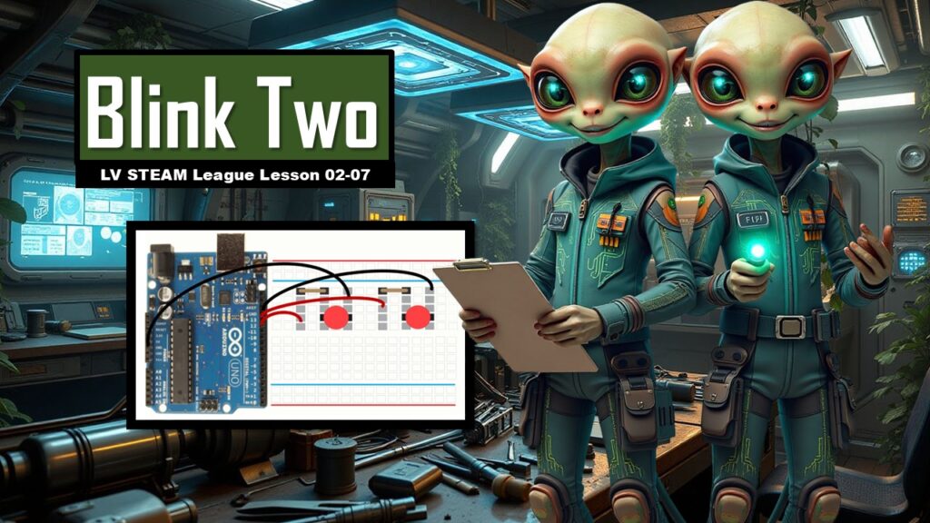
In this lesson students expand on everything they learned in Blink and Blink Extension. They build a circuit with two LEDs, wire each to a different Arduino pin, and write a sketch that makes the LEDs blink in opposite patterns. This is a joyful moment for students because they experience real programming logic shaping real hardware behavior.
This lesson gently introduces multiple variables, controlling multiple outputs, using shared ground, and reading code that grows step by step. Students begin to see how small pieces added together can create more complex behavior—a core STEAM skill.
Student Learning Goals
By the end of this lesson students will be able to
• Build a breadboard circuit with two LEDs and two resistors
• Wire each LED to a separate digital pin
• Understand and use multiple variables in an Arduino sketch
• Configure multiple pins with pinMode
• Control multiple outputs using digitalWrite
• Understand how HIGH and LOW affect behavior
• Upload a program and observe alternating LED patterns
• Feel comfortable modifying and expanding earlier sketches
Materials Needed
Arduino Uno boards
USB cables
Breadboards
4 jumper wires
2 resistors (220 or 330 ohm)
2 LEDs
Student notebooks
Computers with Arduino IDE
Teacher Preparation Notes
Before class, build the final two-LED circuit so you can show students the finished goal.
Make sure students sit at tables with protective mats if surfaces are metal.
Have both LEDs, resistors, and jumper wires ready in sets so students don’t have to search for materials.
Move slowly through wiring since multiple components can feel overwhelming for beginners.
Above all, reassure them. Nothing here is dangerous and mistakes are expected.
Safety Notes
Always unplug the Arduino before changing wiring.
Never allow the Arduino to rest on metal surfaces.
LEDs must be placed with correct polarity (long leg = positive).
Keep drinks and water far from the wiring area.
Double check resistor placement before powering.
Warm Up Activity
Show students the simple two-LED circuit from the slide and ask
What do you think will happen when we run two LEDs at once
Let them guess freely. Any answer is okay.
Use their guesses to build excitement for the challenge.
Lesson Flow
**Step One
Review the Blink Extension Materials**
Remind students of the items from last class
Arduino, breadboard, wires, resistors, and LED.
Teacher tone
Tell them today is the same idea—just doubled.
Familiarity reduces anxiety.
**Step Two
Build the First LED Circuit**
Show the PPT step
Let’s start with the LED and resistor as we have done before.
Guide students
Place LED 1
Attach resistor
Connect LED 1 ground to GND
Confirm orientation
Move around the room quietly checking student work.
**Step Three
Build the Second LED Circuit**
Students repeat the same LED + resistor setup for LED 2.
Reassure them
You are doing the same thing, simply twice.
Nothing new yet—just practice.
**Step Four
Connect Grounds**
Use the PPT slides showing GND connections.
Explain
Both LEDs must share the same ground for the circuit to work.
Ground is like the “return path” that completes the loop.
Have them connect
LED 1 ground → GND
LED 2 ground → GND
**Step Five
Connect the Power Pins**
Using the PPT instructions
Pin 12 → LED 1
Pin 13 → LED 2
Teacher note
Keep this step slow.
Matching pin numbers in code and wiring is the most important skill today.
**Step Six
Open the IDE**
Have students open Arduino IDE.
Explain that we will build the sketch step by step.
**Step Seven
Start with One LED Variable**
Show the first code slide
int led01 = 13;
Explain
Variables store pin numbers so your code is easier to read.
Students type
int led01 = 13;
**Step Eight
Add the Second LED Variable**
Show the next slide
int led01 = 13;
int led02 = 12;
Explain gently
Now we have two lights.
We need two variables.
Students type the second line.
**Step Nine
Understanding setup() With Two Pins**
Show the slide
pinMode(led01, OUTPUT);
pinMode(led02, OUTPUT);
Guide them
Setup tells the Arduino what each pin will do.
Today both pins send power out, so they are both OUTPUT.
Students type both lines inside setup().
**Step Ten
Write the Two-LED Loop**
Show the loop example
digitalWrite(led01, HIGH);
digitalWrite(led02, LOW);
delay(1000);
digitalWrite(led01, LOW);
digitalWrite(led02, HIGH);
delay(1000);
Explain slowly
We are creating an alternating pattern
LED 1 ON / LED 2 OFF
pause
LED 1 OFF / LED 2 ON
pause
They are taking turns.
Teacher reassurance
A simple pattern becomes something exciting when you build it with your hands.
**Step Eleven
Upload the Code**
Have students connect the Arduino and click upload.
Celebrate when they see the alternating blinking.
Encourage students to look closely at the timing and pattern.
**Step Twelve
Understanding Common Grounds and Power Busses**
Show the PPT explanation of the breadboard’s power busses.
Explain
These side rails help you bring power and ground wherever you need it.
Today we used a simple layout, but soon we’ll use these rails to build larger circuits.
**Step Thirteen
Extension: Add More LEDs**
Show the slides that expand code to three and four LEDs.
This is optional but inspiring.
Let students imagine how patterns could grow in complexity.
You can let advanced students try it if they finish early.
Teacher Notes for Each Slide
“This is what we are going to build”
Use this to anchor the lesson goal.
Building the two LED circuits
Emphasize repetition and familiarity.
Connecting pin 12 and 13
Match wiring to code every time.
Code buildup slides
The PPT builds the code piece by piece. Follow the same rhythm.
Alternating blink logic
Use real world examples like turn signals or railroad lights.
Power busses
Keep this simple and visual.
Multi-LED expansions
Encourage creativity but avoid overwhelming hesitant students.
Independent or Group Activity
Option A
Student-Designed Pattern
Have students try different delays
200
500
1200
to make custom alternating rhythms.
Option B
Reverse the Pattern
Have them make LED 2 start ON and LED 1 start OFF.
Option C
Add a Third LED
For advanced students wanting a challenge.
Vocabulary and Concepts
Variable
A word that stores a number (like a pin number).
pinMode
Tells a pin whether to send or receive.
digitalWrite
Turns a pin HIGH or LOW.
Ground (GND)
The return path that completes the circuit.
Power buss
Side rails on the breadboard that carry power or ground.
Wrap Up
Ask students
What was the trickiest part of building two circuits
Did the alternating blink look the way you expected
What pattern would you like to try next
Make space for pride—the wiring and code today are a big milestone.
Exit Ticket
One
Why do both LEDs need to connect to the same ground
Two
What lines in your code control the blinking pattern
Quiz
1. Multiple Choice
What does digitalWrite(led01, HIGH) do
A. Turns LED 1 off
B. Turns LED 1 on
C. Makes both LEDs blink
2. Short Answer
What does pinMode(led02, OUTPUT) mean
3. Multiple Choice
Which pins did we use in this lesson
A. 0 and 1
B. 13 and 12
C. 7 and 8
4. Short Answer
Why do we use resistors
5. Short Answer
What does delay(1000) do
Teacher Reflection
Were students able to manage wiring for two LEDs
Did they make connections between code and hardware
Was there enough time for debugging
Would a printed wiring diagram help next time